
 English
 Spanish
 French
 Arabic
Electric Pole Accessories
- Home
- Products
- Electrical Cross Arms, Pole Line Hardware
- CW-C11 Galvanized Steel Cross Arm with 11 Holes

Organize your aerial cable attachment points with the CW-C11 cross arm with 11 holes. This galvanized steel angle section measures 40 × 40 × 4 × 436 mm and mounts on a compatible pole bracket for parallel overhead line deployment.
You can use its pre-drilled positions for approved dead-ending or suspension arrangements. Combine the cross arm with suitable drop wire clamps, anchor clamps, and pole fixing hardware after checking connection dimensions and design loads.
When you distribute overhead cables from a pole, your attachment points need an organized layout. The CW-C11 cross arm with 11 holes provides a galvanized steel mounting member for arranging compatible line fittings along an aerial route.
You install the angle section on a pole bracket suited to the supporting structure. Its pre-drilled holes provide positions for the connection hardware used in your dead-ending or suspension arrangement. This helps you plan parallel cable routes and separate attachment positions within the available space.
For a drop that branches perpendicular to the main network, the cross arm can receive a compatible FE drop anchoring plate at its end. Confirm the plate connection and complete load arrangement before ordering.
You can select attachment positions to suit your approved cable layout. Check the hole diameter, spacing, and clearance around each fitting so that clamp bails, connectors, or bolts can seat correctly.
The steel body provides the structural mounting member, while the zinc finish helps protect the surface against corrosion. Include the coating requirements for your installation environment in the purchasing specification.
The listed size is 40 × 40 × 4 × 436 mm. Use this specification together with the product drawing to check the bracket interface, available pole space, and attachment positions.
You can plan installations on non-drillable poles, drillable wooden poles, pre-drilled poles, or extension brackets by selecting the corresponding mounting support. The fixing method depends on the pole and bracket; it is not determined by the cross arm alone.
| Parameter | Specification |
|---|---|
| Model | CW-C11 |
| Product | Cross Arm with 11 Holes |
| Material | Galvanized steel |
| Section form | Angle bar |
| Listed size | 40 × 40 × 4 × 436 mm |
| Number of pre-drilled holes | 11 |
| Mounting support | Compatible pole bracket or extension bracket |
| Listed functions | Parallel overhead line deployment; attachment points for dead-ending or suspension |
| Optional end attachment | Compatible FE drop anchoring plate for perpendicular drop cable routing |
Confirm hole diameters, spacing, fastener sizes, bracket interface, coating requirements, and mechanical performance against the assembly drawing. The number of holes does not define the permissible number of loaded cables.
The cross arm supports the connected fittings and transfers their loads into the pole bracket and its fixing system. A drop wire clamp or anchor clamp grips the cable, while the cross arm provides the attachment position for the approved connector arrangement.
For suspension applications, use hardware designed to support the specified cable without applying an unsuitable grip or bend. For dead-ending, review cable tension, load direction, and the capacity of the entire assembly.
Plan the positions of loaded fittings carefully. An attachment near the end of the arm can place different demands on the assembly from an attachment near the support. Review combined and unbalanced loads when you prepare the layout.
Start with your cable layout. Identify the number of cable routes, their directions, and whether each connection requires anchoring or suspension.
Check the pole and support. Record the pole material, profile, dimensions at the mounting height, and whether drilling is permitted. Select a bracket and fixing arrangement approved for that structure.
Match the connecting hardware. Compare clamp bail dimensions, connector geometry, hole sizes, and required clearances. Do not assume that every drop clamp fits directly into every hole.
Review the complete loading. Include the attached cables, fitting positions, tension directions, and relevant environmental loads. Ask for the performance information required by your project before finalizing the order.
Use this sequence to plan the work. Follow the approved assembly drawing and the installation instructions for the bracket, fasteners, banding system, and cable clamps.
Check the angle section, holes, surface finish, and supplied hardware. Confirm that the components match your drawing and have no deformation or damaged contact edges.
For a non-drillable pole, use an approved bracket and banding or clamping arrangement. Where the design specifies a bolted connection, check the permitted drilling or existing hole arrangement before installation.
If you use stainless steel banding, confirm the strap grade, width, thickness, buckle, and bracket interface as a system. Use the specified tensioning tool and installation procedure.
Fit the cross arm to the selected pole or extension bracket. Position it according to the planned cable directions, then secure the connection using the specified fasteners and tightening requirements.
Place the approved drop wire clamps, anchor clamps, or suspension fittings at their designated positions. Use the required connectors and check that moving parts or bails have sufficient clearance.
Install each cable according to its clamp instructions and your line design. Maintain the required bend radius and clearance, and avoid routing an unprotected cable across a metal edge.
Check the cross arm alignment, pole fixing, fasteners, fitting positions, and cable routing. Complete the project’s acceptance checks before placing the assembly into service.
During scheduled inspections, look for cross arm movement, deformation, damaged coating, loose fasteners, and wear at attachment points. Check banding and buckles where they form part of the pole fixing.
Inspect the connected cable clamps separately for seating and sheath damage. If you add or reroute a cable, review the combined loading and attachment layout before using another available hole.
Not automatically. The holes provide attachment positions. The permitted cable arrangement depends on the loads, fitting locations, cross arm performance, bracket, and pole fixing system.
You can include different clamp types in an approved layout. Check each cable specification, connector interface, and load direction, then review the combined assembly requirements.
The product is intended to mount on a compatible support bracket. Use stainless steel banding where the selected bracket and pole fixing design allow it; do not assume the angle section alone provides a suitable banding interface.
The original mounting options include non-drillable poles. Select an appropriate bracket and non-drilling fixing arrangement approved for your pole rather than drilling without authorization.
The cross arm can receive a compatible FE drop anchoring plate at its end. Confirm the plate, fasteners, cable clamp, and load arrangement against the assembly drawing.
Send model CW-C11, quantity, pole details, cable types, attachment layout, and required mounting accessories. Include coating, inspection, packaging, and delivery requirements where applicable.
You can plan your cross arm purchase together with the cable retention and pole fixing hardware needed for the complete installation. The following products serve different roles; confirm direct compatibility and supply scope before ordering.
| Product | Role in Your Installation | Selection Checks |
|---|---|---|
| Drop Wire Clamp – 6 Pair Type | Retain a compatible telecom drop cable at its designated attachment point. | Cable construction and dimensions, grip type, bail connection, and required holding performance. |
| PA560 Plastic Anchor Clamp | Anchor a compatible service cable in a specified dead-end arrangement. | Cable size and shape, clamp rating, connector geometry, and the load on the cross arm. |
| Stainless Steel Banding Straps | Secure a suitable mounting bracket around the pole where a banded fixing is specified. | Steel grade, strap width and thickness, bracket slots, installation tension, and corrosion compatibility. |
| Stainless Steel Buckles | Lock the selected banding strap as part of the approved pole fixing system. | Strap width, buckle type, material, and locking method. |
| CWB-T1 Standard Banding Tool | Tension and finish compatible banding during bracket installation. | Tool capacity, strap dimensions, buckle procedure, and installation instructions. |
For procurement, send the cross arm, cable clamps, bracket, straps, buckles, and fasteners as one bill of materials. This helps you confirm connection details and avoid missing accessories when your installation crew begins work.
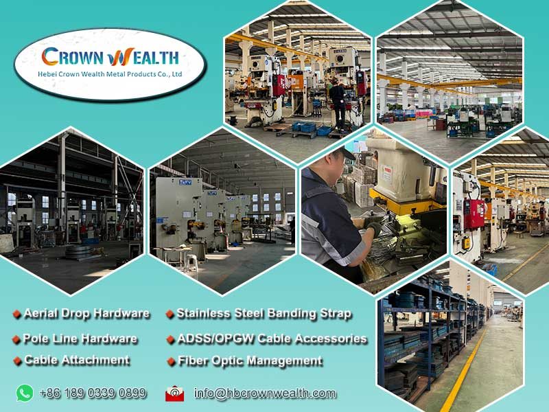
Hbcrownwealth is a professional manufacturer and wholesaler of power and telecommunications overhead line hardware, based in China and serving customers worldwide. You can discuss your galvanized steel cross arm and related aerial hardware requirements with one manufacturing partner.
Share your pole details, cable specifications, and assembly drawing. You can review the required cross arm dimensions, mounting interfaces, and accessory list before finalizing your order.
If your layout requires a different length, hole pattern, or mounting arrangement, discuss it through our OEM / ODM service. Agree on the design, material, finish, and sample requirements before production.
You can specify dimensional checks, coating inspection, and the mechanical documentation required for your project. Confirm quantities, packaging, and delivery requirements alongside the technical specification.
Combine your cross arm inquiry with drop wire clamps, anchor clamps, and stainless steel banding to organize your project purchasing or distribution inventory.
Request a quotation for the CW-C11 cross arm with 11 holes. Contact Hbcrownwealth with your drawing, accessory requirements, order quantity, and delivery destination.
| Parameter | Specification |
|---|---|
| Model | CW-C11 |
| Product | Cross Arm with 11 Holes |
| Material | Galvanized steel |
| Section form | Angle bar |
| Listed size | 40 × 40 × 4 × 436 mm |
| Number of pre-drilled holes | 11 |
| Mounting support | Compatible pole bracket or extension bracket |
| Listed functions | Parallel overhead line deployment; attachment points for dead-ending or suspension |
| Optional end attachment | Compatible FE drop anchoring plate for perpendicular drop cable routing |
Confirm hole diameters, spacing, fastener sizes, bracket interface, coating requirements, and mechanical performance against the assembly drawing. The number of holes does not define the permissible number of loaded cables.
Hbcrownwealth is proudly powered by WordPress


