English
 Spanish
 French
 Arabic
Electric Pole Accessories
- Home
- Products
- Aerial Drop Hardware, Hot Products, Lashing Clamp
- CW-DLC D Cable Lashing Clamp for Messenger Strand
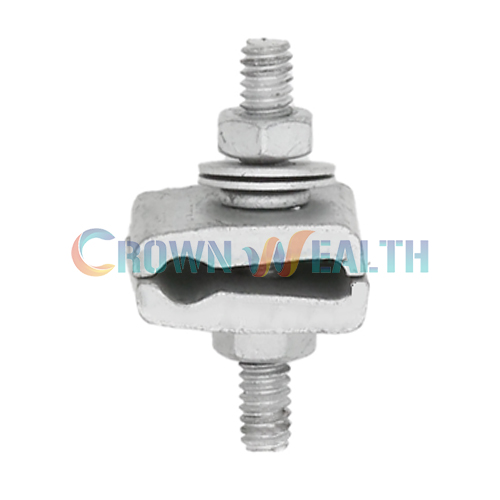
The CW-DLC D Cable Lashing Clamp provides a permanent termination point for lashing wire on messenger strand. You can use it when a lashing wire coil ends or where the continuity of a lashed cable run is interrupted. It helps you secure the wire end around the supporting strand.
This clamp fits messenger strand from 1/4 to 7/16 inch in diameter. Its grooved steel jaws grip the strand, while the stud, washers, and terminating nut secure the lashing wire. For ground wire applications, confirm conductor compatibility and your project’s electrical requirements before selection.
The listed jaw material tensile strength exceeds 50,000 PSI. This value describes the steel material; it does not establish the clamp’s working load limit or the capacity of your installed cable system.
The assembly separates strand clamping from wire termination. Tightening the clamping nut draws the grooved plates onto the messenger strand. The lashing wire then follows the specified route around the strand and into the termination area on the stud. The terminating nut holds the wire against the designated washer and shoulder surfaces.
Correct wire placement matters: pinching, crossed wire, or an unsuitable bend can damage the wire. Use the diagrams below to identify the components, and follow your approved installation procedure for the final assembly.
You can specify the CW-DLC for lashing wire terminations in aerial telecommunications and supported cable installations. Typical positions include the end of a lashing wire coil and planned interruptions in a cable run. For overlashing or ground wire termination, confirm the required washer arrangement and wire compatibility with your project specification.
Before ordering, check the messenger strand diameter, lashing wire material and size, installation arrangement, and coating requirements. The stated 1/4–7/16 inch range refers to the messenger strand, not the cable outside diameter or lashing wire diameter.


For a second lashing wire or a ground wire, use the washer position specified for that configuration. Confirm the arrangement before tightening. Obtain the project’s required tightening values; no installation torque or assembly load rating is stated in this product listing.
During scheduled line inspections, look for clamp movement, loose hardware, damaged wire, corrosion, or contact between a sharp wire end and the cable sheath. Replace damaged components and correct the cause of any movement before returning the assembly to service. Follow your network’s inspection and maintenance procedures.
It secures the end of lashing wire to messenger strand in aerial construction, particularly at coil ends or interruptions in a lashed cable run.
It fits messenger strand from 1/4 to 7/16 inch in diameter, approximately 6.35–11.11 mm. Check the strand diameter when selecting the clamp.
The jaws are annealed 1018 steel, and the stud is Grade 5 steel. The components are mechanically galvanized to the listed ASTM B695, Class 50, Type 1 coating specification.
Ground wire termination is a listed application. Confirm the conductor size, material, washer position, and required electrical performance for your installation before use.
No. It refers to the jaw material tensile strength. Ask for relevant assembly performance data if your project requires a specified holding strength or working load.
Send model CW-DLC, required quantity, messenger strand diameter, wire specification, coating requirements, and delivery destination. Include drawings or inspection requirements for any project-specific request.

Hbcrownwealth is a professional manufacturer and wholesale supplier of power and telecommunications overhead line hardware in China. We support distributors, importers, and contractors with product selection and bulk supply. Contact us with your CW-DLC specifications and quantity to request a quotation and discuss any customization requirements.
| Parameter | Specification |
|---|---|
| Model | CW-DLC |
| Product | D Cable Lashing Clamp |
| Messenger strand diameter | 1/4–7/16 in (approximately 6.35–11.11 mm) |
| Jaw material | Rolled and stamped annealed 1018 steel |
| Stud material | Grade 5 steel |
| Finish | Mechanical galvanizing |
| Coating specification | ASTM B695, Class 50, Type 1 |
| Jaw material tensile strength | Exceeds 50,000 PSI; this is not an assembly working load rating |
| Stud ends | Staked to help prevent disassembly during handling |
The CW-DLC D Cable Lashing Clamp provides a permanent termination point for lashing wire on messenger strand. You can use it when a lashing wire coil ends or where the continuity of a lashed cable run is interrupted. It helps you secure the wire end around the supporting strand.
This clamp fits messenger strand from 1/4 to 7/16 inch in diameter. Its grooved steel jaws grip the strand, while the stud, washers, and terminating nut secure the lashing wire. For ground wire applications, confirm conductor compatibility and your project’s electrical requirements before selection.
The listed jaw material tensile strength exceeds 50,000 PSI. This value describes the steel material; it does not establish the clamp’s working load limit or the capacity of your installed cable system.
The assembly separates strand clamping from wire termination. Tightening the clamping nut draws the grooved plates onto the messenger strand. The lashing wire then follows the specified route around the strand and into the termination area on the stud. The terminating nut holds the wire against the designated washer and shoulder surfaces.
Correct wire placement matters: pinching, crossed wire, or an unsuitable bend can damage the wire. Use the diagrams below to identify the components, and follow your approved installation procedure for the final assembly.
You can specify the CW-DLC for lashing wire terminations in aerial telecommunications and supported cable installations. Typical positions include the end of a lashing wire coil and planned interruptions in a cable run. For overlashing or ground wire termination, confirm the required washer arrangement and wire compatibility with your project specification.
Before ordering, check the messenger strand diameter, lashing wire material and size, installation arrangement, and coating requirements. The stated 1/4–7/16 inch range refers to the messenger strand, not the cable outside diameter or lashing wire diameter.
For a second lashing wire or a ground wire, use the washer position specified for that configuration. Confirm the arrangement before tightening. Obtain the project’s required tightening values; no installation torque or assembly load rating is stated in this product listing.
During scheduled line inspections, look for clamp movement, loose hardware, damaged wire, corrosion, or contact between a sharp wire end and the cable sheath. Replace damaged components and correct the cause of any movement before returning the assembly to service. Follow your network’s inspection and maintenance procedures.
It secures the end of lashing wire to messenger strand in aerial construction, particularly at coil ends or interruptions in a lashed cable run.
It fits messenger strand from 1/4 to 7/16 inch in diameter, approximately 6.35–11.11 mm. Check the strand diameter when selecting the clamp.
The jaws are annealed 1018 steel, and the stud is Grade 5 steel. The components are mechanically galvanized to the listed ASTM B695, Class 50, Type 1 coating specification.
Ground wire termination is a listed application. Confirm the conductor size, material, washer position, and required electrical performance for your installation before use.
No. It refers to the jaw material tensile strength. Ask for relevant assembly performance data if your project requires a specified holding strength or working load.
Send model CW-DLC, required quantity, messenger strand diameter, wire specification, coating requirements, and delivery destination. Include drawings or inspection requirements for any project-specific request.
Hbcrownwealth is a professional manufacturer and wholesale supplier of power and telecommunications overhead line hardware in China. We support distributors, importers, and contractors with product selection and bulk supply. Contact us with your CW-DLC specifications and quantity to request a quotation and discuss any customization requirements.
| Parameter | Specification |
|---|---|
| Model | CW-DLC |
| Product | D Cable Lashing Clamp |
| Messenger strand diameter | 1/4–7/16 in (approximately 6.35–11.11 mm) |
| Jaw material | Rolled and stamped annealed 1018 steel |
| Stud material | Grade 5 steel |
| Finish | Mechanical galvanizing |
| Coating specification | ASTM B695, Class 50, Type 1 |
| Jaw material tensile strength | Exceeds 50,000 PSI; this is not an assembly working load rating |
| Stud ends | Staked to help prevent disassembly during handling |