English
 Spanish
 French
 Arabic
Electric Pole Accessories
- Home
- Products
- Pole Line Bolt
- CW-SR Hot-Dip Galvanized Stay Rod Set
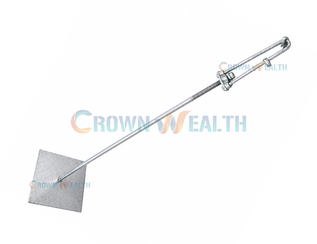
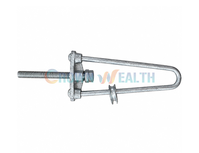
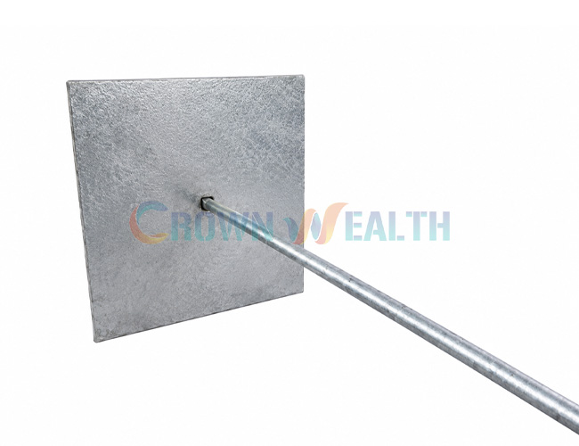
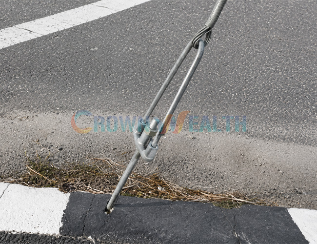
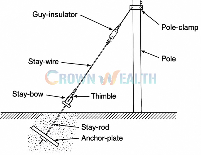
Support your utility pole guying system with the CW-SR stay rod set. Made from hot-dip galvanized steel, the assembly connects your stay wire to the specified ground anchoring arrangement in overhead power and telecommunications projects.
You can select listed rod diameters of 12, 16, 20, 22, or 25 mm, with length options depending on the rod size. Send your drawing, loading requirements, and component list to confirm the right configuration for your project.
Support your utility pole guying system with the CW-SR stay rod set. Made from hot-dip galvanized steel, the assembly connects your stay wire to the specified ground anchoring arrangement in overhead power and telecommunications projects.
You can select listed rod diameters of 12, 16, 20, 22, or 25 mm, with length options depending on the rod size. Send your drawing, loading requirements, and component list to confirm the right configuration for your project.
When your overhead line changes direction or terminates, the pole may need a designed guying system to resist the resulting loads. The CW-SR stay rod set forms part of that system by connecting the stay wire to the specified ground anchoring arrangement.
You can source hot-dip galvanized stay rod assemblies from Hbcrownwealth for power distribution, telecommunications, rural electrification, and utility infrastructure projects. Choose the rod size and complete assembly to suit your approved design, rather than selecting by length alone.
The stay wire carries tension from its pole attachment toward the ground anchorage. The stay rod transfers that force through the specified connection to the anchor or stay plate arrangement. The anchorage and surrounding ground then provide the resistance required by the design.
Your installed performance depends on the complete system: rod, threads, fittings, plate or anchor, soil conditions, and installation geometry. A larger rod diameter alone does not establish the holding capacity of the ground anchorage.
Where your assembly includes a threaded adjustment component, use it only within its specified adjustment range. Maintain the required thread engagement and follow the approved tensioning procedure.
The steel receives a protective zinc coating for corrosion resistance. For your order, specify the coating requirements and inspection documents needed for the intended exposure conditions.
Check ground conditions as well as the above-ground environment. Soil chemistry, moisture, and coating damage can affect buried components, so include these considerations in your project specification.
You can select from listed rod diameters of 12, 16, 20, 22, and 25 mm. The available length range varies by diameter, helping you match your purchasing request to the installation drawing.
A stay rod set may require a stay plate, thimble, washers, nuts, and other connection components according to the selected design. Confirm the bill of materials in your quotation so your team knows exactly what is included.
If your tender requires a specific rod length, thread, end configuration, or plate arrangement, send your drawing for review. You can also discuss material, galvanizing, marking, and packaging requirements before production.
| Listed Rod Diameter (mm) | Listed Length Range (ft) | Reference Length Range (mm) |
|---|---|---|
| 12 | 4–6 | 1200–1800 |
| 16 | 4–6 | 1200–1800 |
| 20 | 6–10 | 1800–3050 |
| 22 | 8–12 | 2440–3660 |
| 25 | 9–12 | 2740–3660 |
Model: CW-SR. Material: steel. Finish: hot-dip galvanized.
The length ranges above reproduce the listed catalog references; the foot and millimeter values are not exact conversions. Specify the required finished diameter and length in one unit system on your purchase drawing. Confirm the steel grade, thread specification, end configuration, plate dimensions, included accessories, and required mechanical performance before ordering.
For each application, confirm that the selected components and ground anchoring design meet your project requirements.
Start with the guying design, including the required tension, stay angle, and connection details. Request the mechanical performance information needed by your project; this listing does not state a universal load rating for all sizes.
Provide the finished rod diameter, total length, threaded length, thread size and pitch, and end geometry. Clearly distinguish metric requirements from inch-based nominal descriptions.
Check plate dimensions, hole sizes, nut and washer specifications, and the stay wire connection. Agree on the included components so your installers receive the assembly described by the drawing.
Have the anchor arrangement selected for the actual site conditions. Embedment, plate orientation, and backfilling requirements should come from the approved ground anchoring design.
Include your quantity, material and coating requirements, dimensional tolerances, required test documents, packaging, and destination. These details help you obtain a quotation that matches your procurement specification.
The following overview helps you plan the work. Your installation team should follow the approved site design and component instructions for excavation, assembly, backfilling, and tensioning.
Check the rod, threads, end connection, plate, nuts, washers, and other supplied fittings against the drawing. Look for deformation, damaged threads, or coating damage before assembly.
Verify the approved position, stay direction, and required clearances. Complete the site checks for buried services before excavation, and use the specified excavation procedure.
Fit the rod and anchoring components according to the drawing. Maintain the specified alignment so the rod carries the intended load without unintended bending at the connection.
Use the designed embedment and plate orientation. Do not select burial depth from the rod length alone.
Inspect the below-ground arrangement before covering it. Backfill and compact as required by the anchoring design, recording any inspections or tests specified for the project.
Use the specified stay wire termination and adjustment components. Apply tension through the approved procedure, maintaining the required thread engagement and checking the pole alignment.
Inspect the accessible connections, rod alignment, adjustment position, and surrounding ground. Complete the required acceptance checks before putting the system into service.
During scheduled inspections, check exposed components for corrosion, bending, loose connections, thread damage, and loss of tension. Look for ground movement or settlement around the anchorage.
If you notice movement or repeated loss of tension, investigate the anchorage and loading before simply retightening the assembly. Arrange repair or replacement according to your utility’s maintenance procedure.
When changing line loads or replacing a pole, review the stay system again. The existing rod and anchorage may not suit the revised design.
The supply scope depends on your selected configuration. Confirm the rod, plate or anchoring connection, thimble, nuts, washers, and any adjustment components against the quotation and assembly drawing.
The stay wire is the tensioned strand running from the pole toward the anchorage. The stay rod forms the connection within the ground anchoring assembly. You need compatible components throughout the load path.
No. The catalog values are reference ranges rather than exact conversions. State the required finished length and unit system on your order drawing.
No. Installed capacity also depends on the steel and threads, connections, plate or anchor design, soil conditions, and installation quality. Select the complete system for your required load.
Use the embedment specified by the site’s anchoring design. There is no single depth suitable for every rod size, ground condition, or stay load.
Yes. Send your drawing, rod dimensions, material grade, thread details, coating requirements, and component list to discuss OEM / ODM production.
Hbcrownwealth is a professional manufacturer and wholesaler of power and telecommunications overhead line hardware, based in China and serving customers worldwide. You can work with us to define a stay rod set order around your utility specification, distribution inventory, or construction project.
Discuss your drawing, dimensions, material selection, and assembly scope directly with our team. Clarifying these details before production helps you avoid mismatched components during installation.
You can specify material documentation, dimensional checks, galvanizing inspection, and mechanical testing required by your purchase. Agree on the acceptance criteria and documents with your order.
Choose a listed size or submit a project-specific design for review. You can also discuss product marking and packaging to suit your warehouse, distribution, or site handling requirements.
Confirm quantities, packing, delivery requirements, and the complete component list together. This gives your purchasing and receiving teams a clear basis for managing the order.
Request your CW-SR stay rod set quotation. Contact Hbcrownwealth with your drawing, required quantity, inspection requirements, and delivery destination.
| Listed Rod Diameter (mm) | Listed Length Range (ft) | Reference Length Range (mm) |
|---|---|---|
| 12 | 4–6 | 1200–1800 |
| 16 | 4–6 | 1200–1800 |
| 20 | 6–10 | 1800–3050 |
| 22 | 8–12 | 2440–3660 |
| 25 | 9–12 | 2740–3660 |
Model: CW-SR. Material: steel. Finish: hot-dip galvanized.
The length ranges above reproduce the listed catalog references; the foot and millimeter values are not exact conversions. Specify the required finished diameter and length in one unit system on your purchase drawing. Confirm the steel grade, thread specification, end configuration, plate dimensions, included accessories, and required mechanical performance before ordering.
When your overhead line changes direction or terminates, the pole may need a designed guying system to resist the resulting loads. The CW-SR stay rod set forms part of that system by connecting the stay wire to the specified ground anchoring arrangement.
You can source hot-dip galvanized stay rod assemblies from Hbcrownwealth for power distribution, telecommunications, rural electrification, and utility infrastructure projects. Choose the rod size and complete assembly to suit your approved design, rather than selecting by length alone.
The stay wire carries tension from its pole attachment toward the ground anchorage. The stay rod transfers that force through the specified connection to the anchor or stay plate arrangement. The anchorage and surrounding ground then provide the resistance required by the design.
Your installed performance depends on the complete system: rod, threads, fittings, plate or anchor, soil conditions, and installation geometry. A larger rod diameter alone does not establish the holding capacity of the ground anchorage.
Where your assembly includes a threaded adjustment component, use it only within its specified adjustment range. Maintain the required thread engagement and follow the approved tensioning procedure.
The steel receives a protective zinc coating for corrosion resistance. For your order, specify the coating requirements and inspection documents needed for the intended exposure conditions.
Check ground conditions as well as the above-ground environment. Soil chemistry, moisture, and coating damage can affect buried components, so include these considerations in your project specification.
You can select from listed rod diameters of 12, 16, 20, 22, and 25 mm. The available length range varies by diameter, helping you match your purchasing request to the installation drawing.
A stay rod set may require a stay plate, thimble, washers, nuts, and other connection components according to the selected design. Confirm the bill of materials in your quotation so your team knows exactly what is included.
If your tender requires a specific rod length, thread, end configuration, or plate arrangement, send your drawing for review. You can also discuss material, galvanizing, marking, and packaging requirements before production.
| Listed Rod Diameter (mm) | Listed Length Range (ft) | Reference Length Range (mm) |
|---|---|---|
| 12 | 4–6 | 1200–1800 |
| 16 | 4–6 | 1200–1800 |
| 20 | 6–10 | 1800–3050 |
| 22 | 8–12 | 2440–3660 |
| 25 | 9–12 | 2740–3660 |
Model: CW-SR. Material: steel. Finish: hot-dip galvanized.
The length ranges above reproduce the listed catalog references; the foot and millimeter values are not exact conversions. Specify the required finished diameter and length in one unit system on your purchase drawing. Confirm the steel grade, thread specification, end configuration, plate dimensions, included accessories, and required mechanical performance before ordering.
For each application, confirm that the selected components and ground anchoring design meet your project requirements.
Start with the guying design, including the required tension, stay angle, and connection details. Request the mechanical performance information needed by your project; this listing does not state a universal load rating for all sizes.
Provide the finished rod diameter, total length, threaded length, thread size and pitch, and end geometry. Clearly distinguish metric requirements from inch-based nominal descriptions.
Check plate dimensions, hole sizes, nut and washer specifications, and the stay wire connection. Agree on the included components so your installers receive the assembly described by the drawing.
Have the anchor arrangement selected for the actual site conditions. Embedment, plate orientation, and backfilling requirements should come from the approved ground anchoring design.
Include your quantity, material and coating requirements, dimensional tolerances, required test documents, packaging, and destination. These details help you obtain a quotation that matches your procurement specification.
The following overview helps you plan the work. Your installation team should follow the approved site design and component instructions for excavation, assembly, backfilling, and tensioning.
Check the rod, threads, end connection, plate, nuts, washers, and other supplied fittings against the drawing. Look for deformation, damaged threads, or coating damage before assembly.
Verify the approved position, stay direction, and required clearances. Complete the site checks for buried services before excavation, and use the specified excavation procedure.
Fit the rod and anchoring components according to the drawing. Maintain the specified alignment so the rod carries the intended load without unintended bending at the connection.
Use the designed embedment and plate orientation. Do not select burial depth from the rod length alone.
Inspect the below-ground arrangement before covering it. Backfill and compact as required by the anchoring design, recording any inspections or tests specified for the project.
Use the specified stay wire termination and adjustment components. Apply tension through the approved procedure, maintaining the required thread engagement and checking the pole alignment.
Inspect the accessible connections, rod alignment, adjustment position, and surrounding ground. Complete the required acceptance checks before putting the system into service.
During scheduled inspections, check exposed components for corrosion, bending, loose connections, thread damage, and loss of tension. Look for ground movement or settlement around the anchorage.
If you notice movement or repeated loss of tension, investigate the anchorage and loading before simply retightening the assembly. Arrange repair or replacement according to your utility’s maintenance procedure.
When changing line loads or replacing a pole, review the stay system again. The existing rod and anchorage may not suit the revised design.
The supply scope depends on your selected configuration. Confirm the rod, plate or anchoring connection, thimble, nuts, washers, and any adjustment components against the quotation and assembly drawing.
The stay wire is the tensioned strand running from the pole toward the anchorage. The stay rod forms the connection within the ground anchoring assembly. You need compatible components throughout the load path.
No. The catalog values are reference ranges rather than exact conversions. State the required finished length and unit system on your order drawing.
No. Installed capacity also depends on the steel and threads, connections, plate or anchor design, soil conditions, and installation quality. Select the complete system for your required load.
Use the embedment specified by the site’s anchoring design. There is no single depth suitable for every rod size, ground condition, or stay load.
Yes. Send your drawing, rod dimensions, material grade, thread details, coating requirements, and component list to discuss OEM / ODM production.
Hbcrownwealth is a professional manufacturer and wholesaler of power and telecommunications overhead line hardware, based in China and serving customers worldwide. You can work with us to define a stay rod set order around your utility specification, distribution inventory, or construction project.
Discuss your drawing, dimensions, material selection, and assembly scope directly with our team. Clarifying these details before production helps you avoid mismatched components during installation.
You can specify material documentation, dimensional checks, galvanizing inspection, and mechanical testing required by your purchase. Agree on the acceptance criteria and documents with your order.
Choose a listed size or submit a project-specific design for review. You can also discuss product marking and packaging to suit your warehouse, distribution, or site handling requirements.
Confirm quantities, packing, delivery requirements, and the complete component list together. This gives your purchasing and receiving teams a clear basis for managing the order.
Request your CW-SR stay rod set quotation. Contact Hbcrownwealth with your drawing, required quantity, inspection requirements, and delivery destination.
| Listed Rod Diameter (mm) | Listed Length Range (ft) | Reference Length Range (mm) |
|---|---|---|
| 12 | 4–6 | 1200–1800 |
| 16 | 4–6 | 1200–1800 |
| 20 | 6–10 | 1800–3050 |
| 22 | 8–12 | 2440–3660 |
| 25 | 9–12 | 2740–3660 |
Model: CW-SR. Material: steel. Finish: hot-dip galvanized.
The length ranges above reproduce the listed catalog references; the foot and millimeter values are not exact conversions. Specify the required finished diameter and length in one unit system on your purchase drawing. Confirm the steel grade, thread specification, end configuration, plate dimensions, included accessories, and required mechanical performance before ordering.
Hbcrownwealth is proudly powered by WordPress