English
 Spanish
 French
 Arabic
Electric Pole Accessories
- Home
- Products
- Anchoring Clamp
- CW-PA4/25 Plastic Tension Clamp for Four-Conductor Service Lines
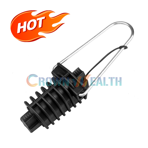
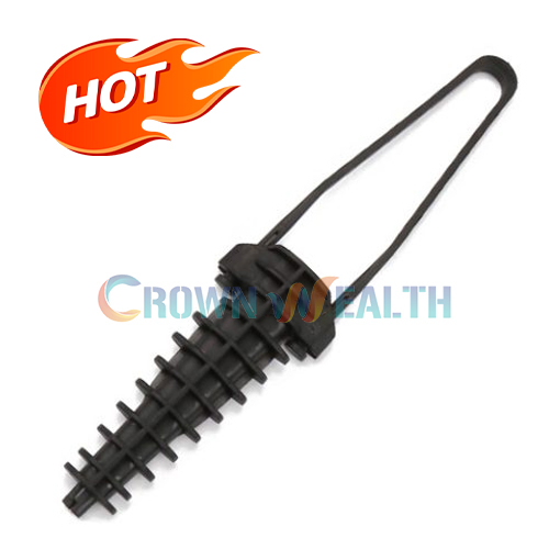
The CW-PA4/25 plastic tension clamp provides an anchoring option for compatible four-conductor service-line arrangements. Its published 4 × 16–25 mm² configuration distinguishes it from two-conductor models. Check the complete cable construction and attachment requirements before placing your order.
| Model | Conductor configuration / cross-section | Breaking load |
|---|---|---|
| CW-PA4/25 | 4 × 16–25 mm² | 2.5 kN |
Reading the specification: 4 × 16–25 mm² means four conductors, each with a nominal cross-section of 16–25 mm². It does not define the insulated outside diameter or overall bundle dimensions.
The 2.5 kN rating is a breaking load. Your allowable working load and installation tension must be established separately for the complete assembly.
| Model | Cross-section entry in the source specification | Listed breaking load |
|---|---|---|
| CW-PA4/50 | 4X16X50 — range requires confirmation | 2.5 kN |
Request the confirmed CW-PA4/50 cable range before selection. The entry above is reproduced as supplied and should not be interpreted as a verified 16–50 mm² range.
The CW-PA4/25 specification gives you a model to evaluate when your service line uses four conductors within the listed cross-section range. Checking conductor count as well as size helps avoid selecting a two-conductor clamp simply because the nominal areas overlap.
The body uses insulating material with high mechanical strength for its cable-holding role. When assessing compatibility, provide the insulation type and outside dimensions so the cable interface can be reviewed alongside the mechanical requirements.
The specified weather-resistant body material supports its use in outdoor service-line hardware. If your installation requires a defined temperature range, UV test or environmental classification, include those requirements in your technical inquiry.
Consider this model for four-conductor overhead service-line anchoring, including new installations and replacement projects where the cable and attachment arrangement have been checked.
| Model | Published configuration | Selection focus |
|---|---|---|
| CW-PA4/25 | 4 × 16–25 mm² | Four-conductor service-line arrangement |
| CW-PA2/25 plastic tension clamp | 2 × 10–35 mm² | Two-conductor configuration in its model table |
The overlapping conductor sizes do not make these models interchangeable. Check conductor layout, insulated dimensions and attachment geometry for your actual installation. For a requirement outside the listed configuration, send your drawing for review.
Obtain the installation instructions for the exact clamp and cable combination before field work. The following checklist helps you prepare the necessary information; it is not a substitute for the approved fitting procedure.
No torque, span length or installation tension is specified on this page. These values depend on your cable system and project design; the breaking load alone is not a basis for selecting them.

Hbcrownwealth is a manufacturer, supplier and wholesaler of overhead hardware for power and telecommunications systems. For this model, you can submit your four-conductor service-line requirements and purchasing quantity for a configuration-specific quotation.
For technical approval, identify the required dimensions, material information, inspection criteria and supporting documents in your inquiry. Ask for confirmation of the proposed supply against those requirements before ordering.
If you need an OEM/ODM review or a nonstandard arrangement, send your drawings and requested changes. Available customization, sample arrangements, MOQ and lead time must be confirmed for the order. Specific production processes, certifications and testing capabilities are not assumed from the model name.
The published configuration is 4 × 16–25 mm²: four conductors, each with a nominal cross-section of 16–25 mm². Confirm their insulated dimensions and arrangement against the clamp before ordering.
CW-PA4/25 lists four conductors at 16–25 mm² each, while the CW-PA2/25 table lists two conductors at 10–35 mm² each. Select by the complete conductor arrangement, not by cross-section alone.
Two-conductor compatibility is not established by the CW-PA4/25 model table. Although the general product description refers to service lines with 2 or 4 conductors, this model’s listed configuration is four conductors. Submit your cable drawing for a specific recommendation.
The published entry needs clarification. It reads 4X16X50, which does not clearly state a cross-section range. Request a confirmed datasheet before specifying CW-PA4/50; do not assume a 16–50 mm² range from this entry.
No. Breaking load is not an allowable working load or installation tension. Your project designer must establish service loads and the applicable design margin for the cable, clamp and anchorage assembly.
The body is described as mechanically strong, weather-resistant insulating material. The published information does not specify a polymer grade or UV test result. Include any required material grade, exposure test or operating temperature range in your inquiry.
NFC33-042 is the standard reference listed for the product; it is not, by itself, evidence of third-party certification. Specify your required edition, test report or certificate so document availability and applicability can be confirmed.
Provide the model, conductor count, individual cross-sections, insulated dimensions, cable drawing and quantity. Add your attachment arrangement, environment and acceptance requirements. For custom supply, include the requested changes so feasibility, MOQ, samples and delivery timing can be reviewed.
Send Hbcrownwealth your four-conductor cable datasheet, required quantity and anchorage drawing using the inquiry form below. If your inquiry concerns CW-PA4/50, identify that model separately and request confirmation of its cable range.
| Model | Conductor configuration / cross-section | Breaking load |
|---|---|---|
| CW-PA4/25 | 4 × 16–25 mm² | 2.5 kN |
Body: mechanically strong, weather-resistant insulating material. Standard reference: NFC33-042.
Breaking load is not an allowable working load or installation tension. Confirm cable fit against the complete conductor arrangement and insulated dimensions.
| Model | Cross-section entry in the source specification | Listed breaking load |
|---|---|---|
| CW-PA4/50 | 4X16X50 — range requires confirmation | 2.5 kN |
Request the confirmed CW-PA4/50 cable range before selection. The entry above is reproduced as supplied and should not be interpreted as a verified 16–50 mm² range.
The CW-PA4/25 plastic tension clamp provides an anchoring option for compatible four-conductor service-line arrangements. Its published 4 × 16–25 mm² configuration distinguishes it from two-conductor models. Check the complete cable construction and attachment requirements before placing your order.
| Model | Conductor configuration / cross-section | Breaking load |
|---|---|---|
| CW-PA4/25 | 4 × 16–25 mm² | 2.5 kN |
Reading the specification: 4 × 16–25 mm² means four conductors, each with a nominal cross-section of 16–25 mm². It does not define the insulated outside diameter or overall bundle dimensions.
The 2.5 kN rating is a breaking load. Your allowable working load and installation tension must be established separately for the complete assembly.
| Model | Cross-section entry in the source specification | Listed breaking load |
|---|---|---|
| CW-PA4/50 | 4X16X50 — range requires confirmation | 2.5 kN |
Request the confirmed CW-PA4/50 cable range before selection. The entry above is reproduced as supplied and should not be interpreted as a verified 16–50 mm² range.
The CW-PA4/25 specification gives you a model to evaluate when your service line uses four conductors within the listed cross-section range. Checking conductor count as well as size helps avoid selecting a two-conductor clamp simply because the nominal areas overlap.
The body uses insulating material with high mechanical strength for its cable-holding role. When assessing compatibility, provide the insulation type and outside dimensions so the cable interface can be reviewed alongside the mechanical requirements.
The specified weather-resistant body material supports its use in outdoor service-line hardware. If your installation requires a defined temperature range, UV test or environmental classification, include those requirements in your technical inquiry.
Consider this model for four-conductor overhead service-line anchoring, including new installations and replacement projects where the cable and attachment arrangement have been checked.
| Model | Published configuration | Selection focus |
|---|---|---|
| CW-PA4/25 | 4 × 16–25 mm² | Four-conductor service-line arrangement |
| CW-PA2/25 plastic tension clamp | 2 × 10–35 mm² | Two-conductor configuration in its model table |
The overlapping conductor sizes do not make these models interchangeable. Check conductor layout, insulated dimensions and attachment geometry for your actual installation. For a requirement outside the listed configuration, send your drawing for review.
Obtain the installation instructions for the exact clamp and cable combination before field work. The following checklist helps you prepare the necessary information; it is not a substitute for the approved fitting procedure.
No torque, span length or installation tension is specified on this page. These values depend on your cable system and project design; the breaking load alone is not a basis for selecting them.
Hbcrownwealth is a manufacturer, supplier and wholesaler of overhead hardware for power and telecommunications systems. For this model, you can submit your four-conductor service-line requirements and purchasing quantity for a configuration-specific quotation.
For technical approval, identify the required dimensions, material information, inspection criteria and supporting documents in your inquiry. Ask for confirmation of the proposed supply against those requirements before ordering.
If you need an OEM/ODM review or a nonstandard arrangement, send your drawings and requested changes. Available customization, sample arrangements, MOQ and lead time must be confirmed for the order. Specific production processes, certifications and testing capabilities are not assumed from the model name.
The published configuration is 4 × 16–25 mm²: four conductors, each with a nominal cross-section of 16–25 mm². Confirm their insulated dimensions and arrangement against the clamp before ordering.
CW-PA4/25 lists four conductors at 16–25 mm² each, while the CW-PA2/25 table lists two conductors at 10–35 mm² each. Select by the complete conductor arrangement, not by cross-section alone.
Two-conductor compatibility is not established by the CW-PA4/25 model table. Although the general product description refers to service lines with 2 or 4 conductors, this model’s listed configuration is four conductors. Submit your cable drawing for a specific recommendation.
The published entry needs clarification. It reads 4X16X50, which does not clearly state a cross-section range. Request a confirmed datasheet before specifying CW-PA4/50; do not assume a 16–50 mm² range from this entry.
No. Breaking load is not an allowable working load or installation tension. Your project designer must establish service loads and the applicable design margin for the cable, clamp and anchorage assembly.
The body is described as mechanically strong, weather-resistant insulating material. The published information does not specify a polymer grade or UV test result. Include any required material grade, exposure test or operating temperature range in your inquiry.
NFC33-042 is the standard reference listed for the product; it is not, by itself, evidence of third-party certification. Specify your required edition, test report or certificate so document availability and applicability can be confirmed.
Provide the model, conductor count, individual cross-sections, insulated dimensions, cable drawing and quantity. Add your attachment arrangement, environment and acceptance requirements. For custom supply, include the requested changes so feasibility, MOQ, samples and delivery timing can be reviewed.
Send Hbcrownwealth your four-conductor cable datasheet, required quantity and anchorage drawing using the inquiry form below. If your inquiry concerns CW-PA4/50, identify that model separately and request confirmation of its cable range.
| Model | Conductor configuration / cross-section | Breaking load |
|---|---|---|
| CW-PA4/25 | 4 × 16–25 mm² | 2.5 kN |
Body: mechanically strong, weather-resistant insulating material. Standard reference: NFC33-042.
Breaking load is not an allowable working load or installation tension. Confirm cable fit against the complete conductor arrangement and insulated dimensions.
| Model | Cross-section entry in the source specification | Listed breaking load |
|---|---|---|
| CW-PA4/50 | 4X16X50 — range requires confirmation | 2.5 kN |
Request the confirmed CW-PA4/50 cable range before selection. The entry above is reproduced as supplied and should not be interpreted as a verified 16–50 mm² range.