English
 Spanish
 French
 Arabic
Electric Pole Accessories
- Home
- Products
- Drop Wire Clamp
- CWC-2PRXD: 1–2 Pair Drop Wire Clamp with Dimpled Shim
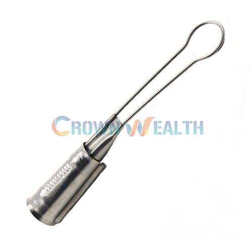
The CWC-2PRXD drop wire clamp supports one- and two-pair telephone drop wire at span clamps, drive hooks and other compatible drop attachments. A shell, wedge and dimpled shim form the compression assembly that holds the wire.
The defining feature of this model is its dimpled shim profile. If your approved hardware list specifies this contact profile, identify CWC-2PRXD explicitly in your inquiry. The CWC-2PRXP uses a plastic shim and should be reviewed as a separate configuration.
| Specification | CWC-2PRXD |
|---|---|
| Product type | 1–2 pair telephone drop wire clamp |
| Shim profile | Dimpled |
| Described clamp construction | Stamped 5052 aluminum |
| Other listed clamp material options | SS201 / SS304; confirm the component material schedule for the selected version |
| Tail wire material | 201/304 stainless steel; grade to be specified |
| Attachment applications | Compatible span clamps, drive hooks and other drop attachments |
| Cable category | One- and two-pair telephone drop wire; dimensional fit to be confirmed |
Holding requirement: the published specification calls for suitable drop wire to be held without slippage until the wire breaks or a maximum load of 555 lb is reached. This test endpoint does not establish a safe working load, installation tension or universal cable rating.
The 5052 aluminum construction and the stainless steel material options should be distinguished in your purchase specification. Confirm the material of the shell, wedge, shim and tail wire individually; a list of available grades does not mean every component uses the same metal.

The formed dimples define the shim surface within the clamping assembly. For your application, evaluate that profile together with the cable jacket, dimensions and construction. A different shim profile should not be treated as an equivalent replacement without checking cable compatibility.
The shell supports the assembly, while the shim and wedge participate in the compression grip. Specifying the complete matched assembly helps you avoid mixing components from different clamp models when purchasing replacement hardware.
The described version uses stamped 5052 aluminum clamp construction with a 201/304 stainless steel tail wire. SS201 and SS304 are also listed as clamp material options. State your required configuration so material selection can be reviewed against the installation environment and project specification.
| Selection point | CWC-2PRXD | CWC-2PRXP |
|---|---|---|
| Specified shim | Dimpled profile | Plastic, non-metallic shim |
| Primary listed application | 1–2 pair telephone drop wire | 1–2 pair telephone drop wire |
| What to confirm | Dimpled contact geometry and component materials | Plastic shim configuration and component materials |
| Replacement decision | Confirm cable fit, holding performance and attachment compatibility before substitution. | |
Choose by the shim requirement and approved cable combination, rather than the similar model names. See the CWC-2PRXP plastic-shim drop wire clamp if your specification calls for a non-metallic insert. The published information does not establish that one version provides higher holding strength than the other.
You can consider this model for aerial telephone service drops, replacement of matching drop hardware and network maintenance at compatible attachment points. The 1–2 pair designation describes the telephone-wire category; it does not define an outside-dimension range.
Before approving a clamp for your project, review these interfaces:
For FTTH fiber drop cable, request a separate review of the cable structure and optical performance requirements. Telephone-wire holding data alone does not demonstrate suitability for fiber cable.
The published criterion describes a grip test that ends when the suitable drop wire breaks or the applied load reaches 555 lb. A wire may break before reaching that value; therefore, the figure should not be presented as a guaranteed breaking strength of every clamp-and-cable combination.
For a meaningful technical comparison, specify the test cable, clamp material configuration, loading procedure and pass/fail criteria. Request confirmation of the applicable test method and available supporting records before using the result in your project approval.
Obtain the model-specific assembly drawing before field installation. The information on this page does not define wedge travel, installation tension, span length or a tool requirement.
These are planning and verification checks, not a substitute for the installation drawing or project procedures.

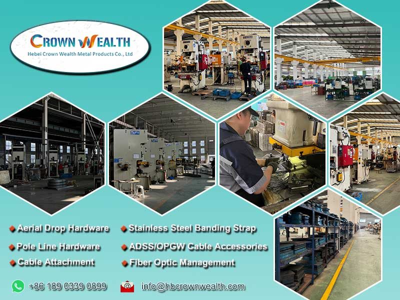
Hbcrownwealth manufactures and supplies overhead line hardware for telecommunications and power applications. For this model, the documented manufacturing details include stamped 5052 aluminum clamp construction and formed 201/304 stainless steel tail wire.
For a wholesale order, agree on a component material schedule and reference drawing. If your procurement process requires samples, dimensional inspection, holding-test records or material documentation, include those requirements in the inquiry so availability and acceptance criteria can be confirmed. Submit any proposed customization as a drawing for review.
The specified shim is different: CWC-2PRXD has a dimpled profile, while CWC-2PRXP has a plastic shim. Select the version required for your approved cable combination; do not assume they are interchangeable.
Not necessarily. The description identifies stamped 5052 aluminum construction and a 201/304 stainless steel tail wire, while the material listing also includes SS201 and SS304 clamp options. Confirm each component’s material for the version you order.
No. Pair count identifies the intended telephone-wire category, but cable dimensions and jacket construction still need to match the clamp. Provide your cable datasheet or cross-section drawing for confirmation.
No. It is the upper endpoint in the published holding requirement, not a stated working-load limit. Establish the allowable load from the approved cable-and-clamp configuration and your project requirements.
Only after the specific fiber cable application is reviewed. Supply the cable geometry, support-member layout and optical acceptance criteria; the telephone-wire description does not verify fiber attenuation performance.
Include CWC-2PRXD, the dimpled shim requirement, cable drawing, component material requirements, quantity and destination. Add the support fitting, required service load and any inspection, testing or packaging requirements.

Send your specification to Hbcrownwealth to request pricing for the CWC-2PRXD dimpled-shim drop wire clamp. For other contact profiles and cable applications, compare our drop wire clamp range.
| Specification | CWC-2PRXD |
|---|---|
| Product type | 1–2 pair telephone drop wire clamp |
| Shim profile | Dimpled |
| Described clamp construction | Stamped 5052 aluminum |
| Other listed clamp material options | SS201 / SS304; confirm the component material schedule for the selected version |
| Tail wire material | 201/304 stainless steel; grade to be specified |
| Attachment applications | Compatible span clamps, drive hooks and other drop attachments |
| Cable category | One- and two-pair telephone drop wire; dimensional fit to be confirmed |
Holding requirement: the published specification calls for suitable drop wire to be held without slippage until the wire breaks or a maximum load of 555 lb is reached. This test endpoint does not establish a safe working load, installation tension or universal cable rating.
The CWC-2PRXD drop wire clamp supports one- and two-pair telephone drop wire at span clamps, drive hooks and other compatible drop attachments. A shell, wedge and dimpled shim form the compression assembly that holds the wire.
The defining feature of this model is its dimpled shim profile. If your approved hardware list specifies this contact profile, identify CWC-2PRXD explicitly in your inquiry. The CWC-2PRXP uses a plastic shim and should be reviewed as a separate configuration.
| Specification | CWC-2PRXD |
|---|---|
| Product type | 1–2 pair telephone drop wire clamp |
| Shim profile | Dimpled |
| Described clamp construction | Stamped 5052 aluminum |
| Other listed clamp material options | SS201 / SS304; confirm the component material schedule for the selected version |
| Tail wire material | 201/304 stainless steel; grade to be specified |
| Attachment applications | Compatible span clamps, drive hooks and other drop attachments |
| Cable category | One- and two-pair telephone drop wire; dimensional fit to be confirmed |
Holding requirement: the published specification calls for suitable drop wire to be held without slippage until the wire breaks or a maximum load of 555 lb is reached. This test endpoint does not establish a safe working load, installation tension or universal cable rating.
The 5052 aluminum construction and the stainless steel material options should be distinguished in your purchase specification. Confirm the material of the shell, wedge, shim and tail wire individually; a list of available grades does not mean every component uses the same metal.
The formed dimples define the shim surface within the clamping assembly. For your application, evaluate that profile together with the cable jacket, dimensions and construction. A different shim profile should not be treated as an equivalent replacement without checking cable compatibility.
The shell supports the assembly, while the shim and wedge participate in the compression grip. Specifying the complete matched assembly helps you avoid mixing components from different clamp models when purchasing replacement hardware.
The described version uses stamped 5052 aluminum clamp construction with a 201/304 stainless steel tail wire. SS201 and SS304 are also listed as clamp material options. State your required configuration so material selection can be reviewed against the installation environment and project specification.
| Selection point | CWC-2PRXD | CWC-2PRXP |
|---|---|---|
| Specified shim | Dimpled profile | Plastic, non-metallic shim |
| Primary listed application | 1–2 pair telephone drop wire | 1–2 pair telephone drop wire |
| What to confirm | Dimpled contact geometry and component materials | Plastic shim configuration and component materials |
| Replacement decision | Confirm cable fit, holding performance and attachment compatibility before substitution. | |
Choose by the shim requirement and approved cable combination, rather than the similar model names. See the CWC-2PRXP plastic-shim drop wire clamp if your specification calls for a non-metallic insert. The published information does not establish that one version provides higher holding strength than the other.
You can consider this model for aerial telephone service drops, replacement of matching drop hardware and network maintenance at compatible attachment points. The 1–2 pair designation describes the telephone-wire category; it does not define an outside-dimension range.
Before approving a clamp for your project, review these interfaces:
For FTTH fiber drop cable, request a separate review of the cable structure and optical performance requirements. Telephone-wire holding data alone does not demonstrate suitability for fiber cable.
The published criterion describes a grip test that ends when the suitable drop wire breaks or the applied load reaches 555 lb. A wire may break before reaching that value; therefore, the figure should not be presented as a guaranteed breaking strength of every clamp-and-cable combination.
For a meaningful technical comparison, specify the test cable, clamp material configuration, loading procedure and pass/fail criteria. Request confirmation of the applicable test method and available supporting records before using the result in your project approval.
Obtain the model-specific assembly drawing before field installation. The information on this page does not define wedge travel, installation tension, span length or a tool requirement.
These are planning and verification checks, not a substitute for the installation drawing or project procedures.
Hbcrownwealth manufactures and supplies overhead line hardware for telecommunications and power applications. For this model, the documented manufacturing details include stamped 5052 aluminum clamp construction and formed 201/304 stainless steel tail wire.
For a wholesale order, agree on a component material schedule and reference drawing. If your procurement process requires samples, dimensional inspection, holding-test records or material documentation, include those requirements in the inquiry so availability and acceptance criteria can be confirmed. Submit any proposed customization as a drawing for review.
The specified shim is different: CWC-2PRXD has a dimpled profile, while CWC-2PRXP has a plastic shim. Select the version required for your approved cable combination; do not assume they are interchangeable.
Not necessarily. The description identifies stamped 5052 aluminum construction and a 201/304 stainless steel tail wire, while the material listing also includes SS201 and SS304 clamp options. Confirm each component’s material for the version you order.
No. Pair count identifies the intended telephone-wire category, but cable dimensions and jacket construction still need to match the clamp. Provide your cable datasheet or cross-section drawing for confirmation.
No. It is the upper endpoint in the published holding requirement, not a stated working-load limit. Establish the allowable load from the approved cable-and-clamp configuration and your project requirements.
Only after the specific fiber cable application is reviewed. Supply the cable geometry, support-member layout and optical acceptance criteria; the telephone-wire description does not verify fiber attenuation performance.
Include CWC-2PRXD, the dimpled shim requirement, cable drawing, component material requirements, quantity and destination. Add the support fitting, required service load and any inspection, testing or packaging requirements.
Send your specification to Hbcrownwealth to request pricing for the CWC-2PRXD dimpled-shim drop wire clamp. For other contact profiles and cable applications, compare our drop wire clamp range.
| Specification | CWC-2PRXD |
|---|---|
| Product type | 1–2 pair telephone drop wire clamp |
| Shim profile | Dimpled |
| Described clamp construction | Stamped 5052 aluminum |
| Other listed clamp material options | SS201 / SS304; confirm the component material schedule for the selected version |
| Tail wire material | 201/304 stainless steel; grade to be specified |
| Attachment applications | Compatible span clamps, drive hooks and other drop attachments |
| Cable category | One- and two-pair telephone drop wire; dimensional fit to be confirmed |
Holding requirement: the published specification calls for suitable drop wire to be held without slippage until the wire breaks or a maximum load of 555 lb is reached. This test endpoint does not establish a safe working load, installation tension or universal cable rating.