English
 Spanish
 French
 Arabic
An overhead fiber optic cable system, also called an aerial fiber optic cable system, carries optical fiber cables above ground on poles or towers. It combines the cable with supporting structures, suspension or anchoring hardware, splice closures, and cable management accessories.
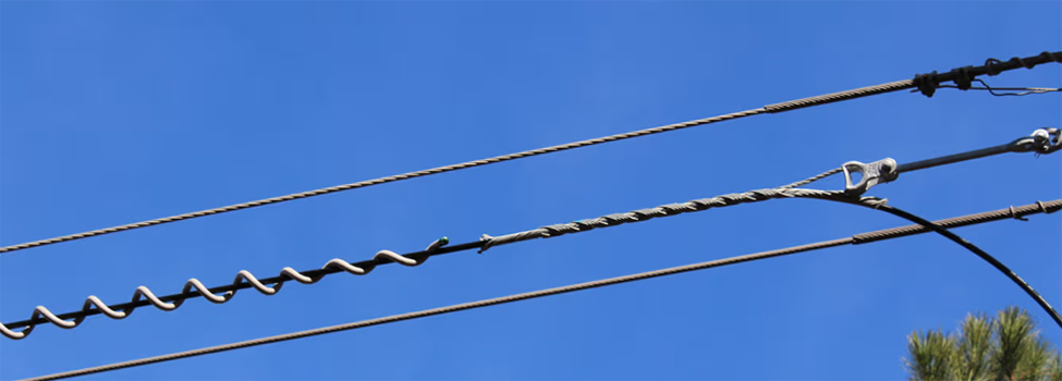
For your project, the most important starting point is the cable construction. ADSS, lashed aerial cable, figure-eight cable, and OPGW use different support arrangements. Choosing compatible hardware helps you protect the cable and avoid unnecessary installation rework.
This guide explains the main cable types, the functions of aerial fiber optic cable hardware, and the information you need before purchasing.
What Makes Up an Overhead Fiber Optic Cable System?
An aerial fiber route needs more than cable and poles. Each component performs a specific function within the installation.
The main elements include:
- Fiber optic cable: Carries optical signals between network locations.
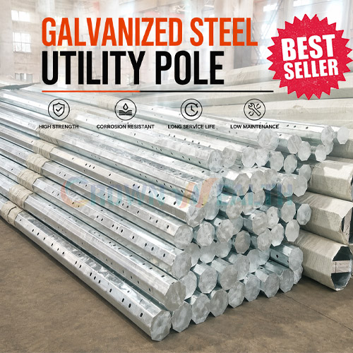
- Poles or towers: Support the route and its attached equipment.
- Suspension and anchoring hardware: Support the cable or transfer its tension to the structure.
- Messenger and lashing components: Support cables in strand-and-lash installations.
- Splice closures and terminal equipment: Protect connections and provide distribution points.
- Downlead clamps and slack storage: Manage cable routing and reserve cable at designated locations.
Not every system uses every component. For example, ADSS does not require a separate messenger strand, while a lashed aerial installation does.
Main Types of Aerial Fiber Optic Cable
ADSS: All-Dielectric Self-Supporting Cable
ADSS cable supports itself between attachment points without a separate metallic messenger. Its nonmetallic strength members carry the specified mechanical load.
ADSS installations require suspension and dead-end assemblies selected for the cable diameter, construction, and design conditions.
When considering ADSS near electrical infrastructure, confirm the cable’s suitability and placement with the cable manufacturer and network designer. “All-dielectric” does not remove the need to assess the electrical environment.
Strand-and-Lash Cable
A strand-and-lash installation uses a separate messenger strand to support the fiber optic cable. Lashing wire secures the cable to that strand.
This arrangement requires hardware for both the messenger and the lashing system. Cable supports, strand attachments, and lashing wire terminations perform different functions and should be specified accordingly.
Figure-Eight Cable
Figure-eight cable combines the optical cable section and an integral supporting messenger in a figure-eight profile.
The supporting section may use different materials depending on the cable design. Select attachment hardware for the actual messenger construction and dimensions rather than the overall cable appearance.
Corning identifies ADSS, strand-and-lash, and figure-eight cable as distinct aerial options in its aerial cable selection overview.
OPGW: Optical Ground Wire
OPGW combines optical fibers with the functions of an overhead ground wire on a power transmission line.
Its design must address both communication requirements and electrical duties, including the specified fault-current conditions. It requires dedicated hardware and installation procedures. See AFL’s OPGW overview for an explanation of these combined functions.
OPGW is a specialized utility application, rather than a general substitute for an FTTH drop cable.
Where Does FTTH Fit?
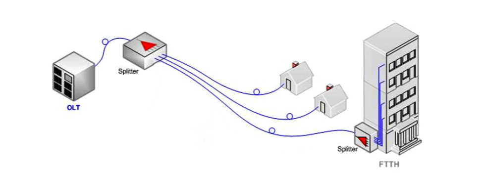
FTTH means Fiber to the Home; it describes a network application, not a cable construction.
An FTTH network may include aerial distribution cables and smaller subscriber drop cables. Each section needs hardware compatible with its cable type, dimensions, and mechanical requirements.
Cable Types and Supporting Hardware at a Glance
| Cable arrangement | How it is supported | Hardware to evaluate |
|---|---|---|
| ADSS | The cable’s own strength members carry the span load | Compatible suspension clamps, dead-end assemblies, and pole attachments |
| Strand-and-lash | A separate messenger supports the cable | Strand fittings, lashing wire, lashing clamps, and cable supports |
| Figure-eight | An integral messenger supports the optical cable section | Fittings matched to the messenger and cable design |
| OPGW | The cable forms part of the overhead ground-wire system | OPGW-specific suspension, dead-end, bonding, and associated assemblies |
| Aerial subscriber drop | Depends on the selected drop-cable construction | Compatible drop clamps and attachment fittings |
Use this table to identify the appropriate product family. Final selection requires the cable datasheet and project design.
Essential Overhead Fiber Optic Cable Hardware
Suspension Clamps
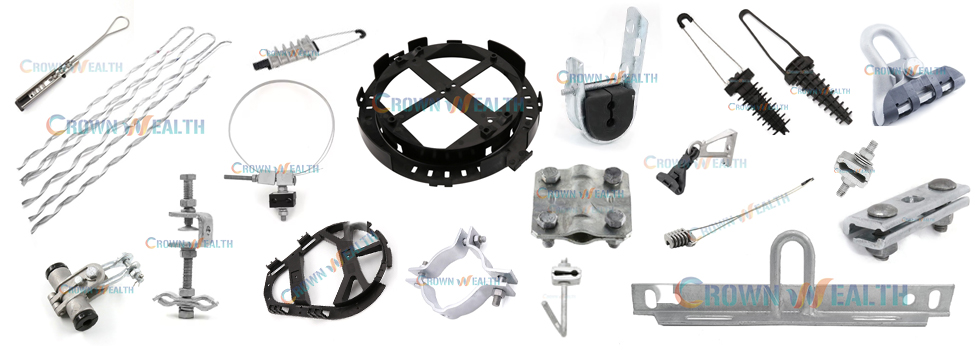
Suspension clamps support compatible cable at intermediate points along the route.
A J-hook suspension clamp is one option for specified ADSS applications. Other routes may require preformed suspension assemblies or a different support design.
Confirm cable compatibility, permitted line angle, loading conditions, and the required attachment arrangement. A suspension clamp should not be assumed to replace a dead-end assembly.
Anchoring Clamps and Preformed Dead Ends
Anchoring hardware transfers cable or messenger tension to the supporting structure at designated points.
The appropriate assembly depends on what it grips. A guy-strand grip, an ADSS dead end, and an OPGW dead end are not interchangeable simply because they have a similar shape.
Select the assembly using the specified cable or strand construction, dimensions, and mechanical requirements.
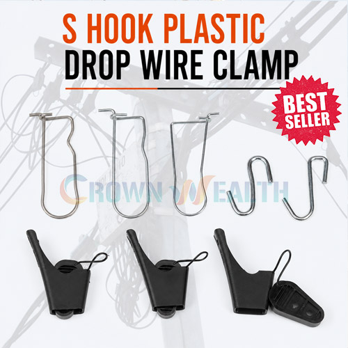
Drop Wire Clamps
Drop wire clamps secure compatible subscriber cables at designated attachment points in aerial access networks.
For flat cables, provide width and thickness. For round cables, provide outside diameter. Also confirm jacket construction, strength-member arrangement, and the intended gripping method.
Downlead Clamps
Downlead clamps retain cable as it runs down a pole or tower toward a splice closure or another connection point.
They manage the downlead route; they do not automatically provide the function of a tension dead end. Choose the correct cable range and pole or tower mounting arrangement.
Review Hbcrownwealth’s ADSS and OPGW downlead clamps for product information.
Span Clamps and Lashing Wire Clamps
These fittings serve different purposes.
A telecom span clamp commonly provides an attachment point on a messenger strand for compatible drop hardware. A lashing wire clamp secures the terminating lashing wire in a lashed cable installation.
For example, the CW-DLC D Cable Lashing Clamp belongs to the lashing system. It should not be described as a universal suspension clamp installed at fixed intervals along every fiber route.
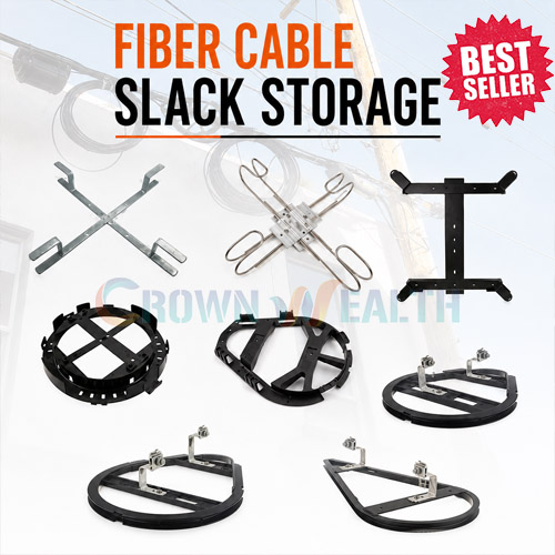
Fiber Optic Cable Slack Storage
Slack storage hardware organizes reserve cable for planned maintenance, splicing, or repair work.
Choose a storage arrangement that accommodates the cable’s minimum bend radius and the required reserve length. Stored slack provides working cable for those tasks; it does not guarantee that a future route extension can be completed without additional cable.
See Hbcrownwealth’s fiber optic cable slack storage for an example.
Pole Bands, Brackets, and Crossarms
These components provide mounting interfaces between the structure and the cable hardware.
Their dimensions and capacity must suit the pole, attached assemblies, and project loads. Crossarms are used where the design calls for them; they are not required at every fiber attachment point.
How to Select Hardware for Your Aerial Fiber Route
Start with the cable and route design, then select the hardware as a compatible assembly.
Before requesting a quotation, collect the following information:
| Selection factor | Information to provide |
|---|---|
| Cable construction | ADSS, figure-eight, lashed cable, OPGW, or subscriber drop |
| Cable dimensions | Outside diameter, or width and thickness where applicable |
| Cable properties | Weight, jacket construction, and relevant strength-member details |
| Route geometry | Span lengths, changes in direction, and termination locations |
| Design conditions | Relevant wind, ice, temperature, and loading requirements |
| Supporting structure | Pole or tower type, dimensions, and mounting details |
| Environmental exposure | Coastal, industrial, or other relevant conditions |
| Documentation | Drawings, required test records, and project specifications |
Two cables with the same diameter may still require different fittings. Likewise, hardware approved for one span arrangement should not automatically be used on another.
Is Aerial Fiber Installation More Cost-Effective Than Underground Installation?
Aerial installation can reduce excavation work where suitable poles and attachment rights are available. However, the final cost depends on the route.
Your comparison should include:
- Pole access and attachment approvals.
- Existing pole condition and structural capacity.
- Required pole modifications or replacements.
- Cable and hardware costs.
- Site access and installation equipment.
- Vegetation management and ongoing maintenance.
- Exposure to storms, traffic incidents, and other route risks.
A fixed savings percentage cannot represent every project. Compare the complete installed and maintenance costs for your proposed aerial and underground routes.
Typical Installation Planning and Acceptance
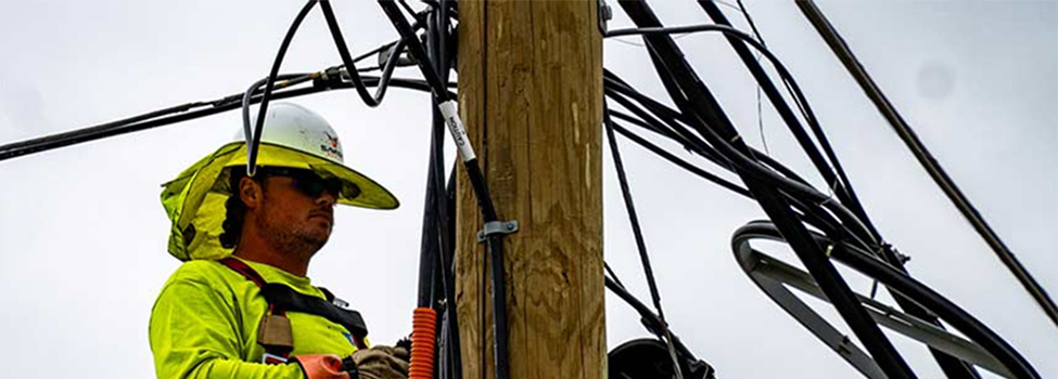
Installation methods vary by cable type. The following sequence provides a planning framework rather than a universal construction procedure.
- Survey the route. Confirm access, supporting structures, crossings, clearances, and proposed connection points.
- Complete the design review. Check pole capacity, cable selection, loading, attachment arrangements, and required approvals.
- Prepare the hardware schedule. Identify suspension points, dead ends, drop attachments, downleads, and slack storage.
- Install the cable using its specified procedure. Observe the manufacturer’s pulling-tension, bending, handling, and sag requirements.
- Complete connections and cable management. Install closures, secure downleads, and organize reserve cable.
- Inspect and test the completed route. Record mechanical checks and perform the optical acceptance tests required by the project.
Corning’s ADSS installation procedure emphasizes planning and checking whether existing poles can accept the additional cable.
Pole height, fitting spacing, pulling limits, and reserve cable length must come from the applicable design and product instructions. They should not be assigned as universal values.
Inspection and Maintenance Priorities
A useful inspection program covers both the cable and its supporting hardware.
Look for visible jacket damage, displaced fittings, loose or deteriorated attachments, damaged closures, and poorly retained slack loops. Compare the installation with its original records when investigating changes in sag or cable position.
Bonding and grounding requirements depend on the system’s metallic components and the approved electrical design. ADSS, metallic messenger systems, and OPGW require different considerations.
Keep drawings, part numbers, inspection records, and optical test results together so maintenance teams can identify the installed assembly.
Frequently Asked Questions
Are overhead and aerial fiber optic cable systems the same?
Yes. Both terms generally describe fiber optic cables installed above ground on supporting structures such as poles or towers.
Does every aerial fiber optic cable need a messenger wire?
No. ADSS supports itself without a separate messenger. Strand-and-lash installations use a separate supporting strand, while figure-eight cables incorporate a messenger into their construction.
Is FTTH a type of aerial cable?
No. FTTH describes a fiber connection to a home. The network can use different cable constructions and installation methods.
Can the same hardware be used for ADSS and OPGW?
Do not assume so. ADSS and OPGW have different constructions and service requirements. Use assemblies specified for the exact cable and application.
How much spare fiber optic cable should you leave?
Use the project’s maintenance and splicing requirements together with the cable manufacturer’s handling limits. There is no single reserve length suitable for every route or closure location.
What information is needed to select overhead fiber hardware?
Provide the cable datasheet, route geometry, design loads, pole or tower details, and required hardware quantities. Include drawings or existing part numbers when replacing installed components.
Source Aerial Fiber Optic Cable Hardware from Hbcrownwealth
Hbcrownwealth manufactures and supplies hardware for overhead power and communication systems, including drop wire clamps, suspension fittings, anchoring hardware, pole attachments, and cable management accessories.
For your project, provide the cable specification and route requirements so the relevant hardware options can be reviewed together. If you require a customized component, include the drawing and acceptance requirements for evaluation.
Contact Hbcrownwealth to discuss your overhead fiber optic cable hardware requirements and request a quotation.