English
 Spanish
 French
 Arabic
Electric Pole Accessories
- Home
- Products
- Pole Band, Utility Pole
- CW-SP1214 Galvanized Steel Single Offset Pole Band
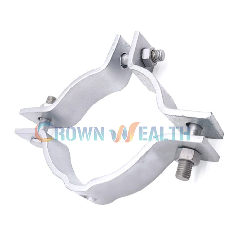
Mount your pole line hardware with the CW-SP1214 single offset pole band, designed for pole diameters of 304–330 mm. Made from galvanized steel, this assembly provides an offset attachment point for secondary rack mounting, guying, and dead-ending applications.
Use it with compatible hardware on metal poles, pipe masts, or conduit where your installation design permits. Before ordering, confirm the pole diameter at the mounting position, attachment dimensions, and required loading.
Mount your pole line hardware with the CW-SP1214 single offset pole band, designed for pole diameters of 304–330 mm. Made from galvanized steel, this assembly provides an offset attachment point for secondary rack mounting, guying, and dead-ending applications.
Use it with compatible hardware on metal poles, pipe masts, or conduit where your installation design permits. Before ordering, confirm the pole diameter at the mounting position, attachment dimensions, and required loading.
When you attach a secondary rack or other line fitting to a pole, you need a mounting arrangement that matches the pole and the direction of the applied load.
The CW-SP1214 wraps around the pole and provides an offset connection point for your hardware. Its formed band sections are secured with fasteners, creating a clamped attachment around the pole surface.
You can use this galvanized steel pole band in an approved power distribution or telecommunications installation. Match the complete assembly—including the band, fasteners, attached fitting, and pole—to your project requirements.
The band sections fit around your pole. As you tighten the connecting fasteners according to the installation specification, the assembly clamps against the pole surface.
The offset section positions the attachment point away from that surface. This gives you a connection location for compatible racks or line hardware.
Correct fit is essential. An oversized band may not clamp properly, while an undersized band may prevent correct assembly. You should also check the offset geometry and mounting-hole dimensions against the fitting you plan to install.
You get a steel pole band with a protective zinc finish for outdoor use. The product’s listed surface treatment is hot-dip galvanizing to ASTM A153.
When preparing your purchase specification, include any coating inspection or documentation requirements. This helps you define what your receiving team should check when the order arrives.
The CW-SP1214 is listed for poles measuring 304–330 mm at the installation position.
Measure the actual mounting location, particularly on a tapered pole. The diameter at ground level may differ from the diameter where you intend to fit the band.
The single offset design provides a mounting position on one side of the assembly. You can align this position with your secondary rack, guy attachment, or dead-end fitting according to the approved layout.
The bolted arrangement allows you to assemble the band around a compatible pole. Confirm the fastener dimensions, grade, and supply scope before ordering so that your installation crew receives the correct components.
| Parameter | Specification |
|---|---|
| Model | CW-SP1214 |
| Product name | Single Offset Pole Band |
| Material | Galvanized steel |
| Surface treatment | Hot-dip galvanizing |
| Listed coating specification | ASTM A153 |
| Minimum pole diameter | 304 mm |
| Maximum pole diameter | 330 mm |
| Configuration | Single offset |
| Listed applications | Secondary rack mounting, guying, and dead-ending |
| Listed mounting structures | Metal poles, pipe masts, or conduit, subject to installation suitability |
Confirm the band width, thickness, offset dimensions, hole sizes, fastener details, and required mechanical performance against the approved drawing. Pole diameter alone does not establish the capacity of the installed assembly.
You can use the offset attachment point to mount a compatible secondary rack. Check the rack connection, available clearance, and load direction before selecting the assembly.
For a replacement installation, compare the existing mounting dimensions with the proposed pole band rather than selecting by appearance alone.
A pole band can provide a connection point for compatible guying hardware where specified by your line design.
Review the guy direction, connection geometry, and design load together. The pole, band, fasteners, and attached hardware must suit the complete arrangement.
You can specify the CW-SP1214 for approved dead-ending arrangements on suitable supporting structures.
Confirm the expected loading and attachment details before purchase. Do not treat the pole diameter range as a dead-end load rating.
The listed applications include metal poles, pipe masts, and conduit. Check the structure’s diameter, shape, wall construction, and ability to accept the intended clamping and attachment loads.
If your project uses a different pole material or profile, send the details for review before choosing this model.
Start by measuring the pole diameter at the exact mounting height. For a tapered pole, record the position as well as the measurement.
Next, identify the hardware you want to attach. A secondary rack and a guy fitting may require different mounting geometry, even when they fit the same pole.
Then, check these details:
For additional selection guidance, read our guide to choosing pole band clamps.
Use the following sequence to plan your work. Follow the approved installation drawing and tightening requirements for the supplied assembly.
Inspect the band sections and fasteners before installation. Look for deformation, damaged threads, sharp damage, or coating defects that require attention.
Confirm that the model and supplied components match your installation specification.
Measure the pole at the intended mounting height. Check that the position provides the required clearance and aligns with the hardware you will attach.
For the CW-SP1214, the listed pole diameter range is 304–330 mm.
Place the sections around the pole and orient the offset attachment point according to your drawing.
Support the components while you insert the specified connecting fasteners. Keep the sections aligned, and do not force an unsuitable band onto the pole.
Tighten the fasteners progressively using the approved sequence and values.
Check that the assembly seats correctly and remains aligned as you tighten it. Do not select a tightening torque based only on bolt appearance or diameter.
Attach the secondary rack or other specified fitting using the correct connection hardware.
Verify the attachment orientation and clearance before applying the intended service load.
Inspect the assembled connection, fasteners, and band position. Confirm that the installation meets your project’s acceptance requirements.
Record the checks required by your maintenance or commissioning procedure.
During routine inspections, check your pole band clamp for movement, deformation, corrosion, and loose or damaged fasteners.
Inspect the zinc coating and look closely at contact areas around the pole and attached fitting. If you find movement or damage, investigate the cause before tightening or replacing components.
After replacing a rack or other accessory, review the connection again. A change in hardware can also change the load direction or clearance required by the installation.
A single offset pole band provides an offset attachment position on one side of the assembly. A double offset design provides additional offset attachment positions. Choose the configuration according to your hardware layout and load directions, and verify the drawing before ordering.
Use the actual specification when selecting the product. The listed pole diameter range for this model is 304–330 mm. Do not infer a different range from the model name.
The CW-SP1214 described here is made from galvanized steel. Its listed finish is hot-dip galvanizing. If your project calls for another material, include that requirement in your inquiry.
Confirm the complete supply scope in your quotation. Ask for the assembly drawing and fastener list so you can check the quantities, sizes, grades, and coating requirements.
The current product listing does not provide an assembly load rating. Send your required load and attachment arrangement so the relevant performance requirements can be reviewed before ordering.
You can discuss custom pole sizes, band dimensions, offset geometry, mounting holes, and packaging through our OEM / ODM service. Provide a drawing and project requirements for review.
Your single offset pole band is one part of a complete overhead line installation. Depending on your project, you may also need hardware for guy wire connections, cable suspension, and reserve cable management.
Hbcrownwealth is a professional manufacturer and wholesaler of power and telecommunications overhead line hardware, based in China and serving customers worldwide. You can coordinate the following products with your pole band order to simplify project purchasing.
| Product | How You May Use It | What to Check Before Ordering |
|---|---|---|
| CW-GC-3 Three Bolt Guy Clamp | Secure guy strand in an approved guy wire termination arrangement. | Strand diameter, clamp configuration, and required holding performance. |
| CW-TNR Straight Thimble Eye Bolt | Provide a through-pole eye connection for guying hardware where specified by your design. | Bolt diameter, shank length, pole construction, and load direction. |
| CW-DP Double Offset Pole Bands | Select an alternative band configuration when your layout requires additional offset attachment positions. | Pole diameter, offset geometry, mounting holes, and attachment loads. |
| J Hook Suspension Clamp | Support compatible ADSS fiber optic cable at intermediate poles along your telecom route. | Cable diameter, mounting arrangement, span conditions, and mechanical requirements. |
| CW-GSOB Fiber Optic Cable Slack Storage Pole Bracket | Organize reserve fiber optic cable at planned splice and maintenance locations. | Cable bend radius, reserve length, available space, and pole fixing details. |
When you prepare your bill of materials, check how each component connects and carries its intended load. These products serve different functions within your project; direct compatibility with the CW-SP1214 should be confirmed against your assembly drawing.
You can send us your pole dimensions, cable or strand specifications, connection drawings, quantities, and inspection requirements. Our team can help you review product selection, discuss OEM / ODM requirements, and coordinate materials, finishes, packaging, and supply scope.
Source your pole bands and related overhead hardware through one manufacturing partner. Contact Hbcrownwealth to discuss your project requirements and request a quotation.
When you purchase pole line hardware, you need more than a matching product name. You need dimensions, materials, and supply details that your installation and procurement teams can verify.
Hbcrownwealth is a professional manufacturer and wholesale supplier of power and telecommunications overhead line hardware in China, serving customers worldwide. You can work with us on standard product selection and project-specific requirements for your single offset pole band order.
You can discuss the pole diameter, attachment drawing, coating, and fastener requirements directly with our team. This helps you define the assembly before production and purchasing decisions are finalized.
If the standard CW-SP1214 does not match your project, share your required dimensions or drawing. You can discuss changes to the formed profile, mounting arrangement, finish, branding, and packaging.
You can specify the dimensional checks, material documentation, coating inspection, and mechanical testing your order requires. Agreeing on these details gives your receiving team a clear basis for acceptance.
Whether you are building inventory or sourcing for an installation project, you can discuss quantities, related pole line hardware, packaging, and delivery requirements together.
Request your single offset pole band quotation. Contact Hbcrownwealth with your pole diameter, attachment drawing, order quantity, and delivery destination.
| Parameter | Specification |
|---|---|
| Model | CW-SP1214 |
| Product name | Single Offset Pole Band |
| Material | Galvanized steel |
| Surface treatment | Hot-dip galvanizing |
| Listed coating specification | ASTM A153 |
| Minimum pole diameter | 304 mm |
| Maximum pole diameter | 330 mm |
| Configuration | Single offset |
| Listed applications | Secondary rack mounting, guying, and dead-ending |
| Listed mounting structures | Metal poles, pipe masts, or conduit, subject to installation suitability |
Confirm the band width, thickness, offset dimensions, hole sizes, fastener details, and required mechanical performance against the approved drawing. Pole diameter alone does not establish the capacity of the installed assembly.
When you attach a secondary rack or other line fitting to a pole, you need a mounting arrangement that matches the pole and the direction of the applied load.
The CW-SP1214 wraps around the pole and provides an offset connection point for your hardware. Its formed band sections are secured with fasteners, creating a clamped attachment around the pole surface.
You can use this galvanized steel pole band in an approved power distribution or telecommunications installation. Match the complete assembly—including the band, fasteners, attached fitting, and pole—to your project requirements.
The band sections fit around your pole. As you tighten the connecting fasteners according to the installation specification, the assembly clamps against the pole surface.
The offset section positions the attachment point away from that surface. This gives you a connection location for compatible racks or line hardware.
Correct fit is essential. An oversized band may not clamp properly, while an undersized band may prevent correct assembly. You should also check the offset geometry and mounting-hole dimensions against the fitting you plan to install.
You get a steel pole band with a protective zinc finish for outdoor use. The product’s listed surface treatment is hot-dip galvanizing to ASTM A153.
When preparing your purchase specification, include any coating inspection or documentation requirements. This helps you define what your receiving team should check when the order arrives.
The CW-SP1214 is listed for poles measuring 304–330 mm at the installation position.
Measure the actual mounting location, particularly on a tapered pole. The diameter at ground level may differ from the diameter where you intend to fit the band.
The single offset design provides a mounting position on one side of the assembly. You can align this position with your secondary rack, guy attachment, or dead-end fitting according to the approved layout.
The bolted arrangement allows you to assemble the band around a compatible pole. Confirm the fastener dimensions, grade, and supply scope before ordering so that your installation crew receives the correct components.
| Parameter | Specification |
|---|---|
| Model | CW-SP1214 |
| Product name | Single Offset Pole Band |
| Material | Galvanized steel |
| Surface treatment | Hot-dip galvanizing |
| Listed coating specification | ASTM A153 |
| Minimum pole diameter | 304 mm |
| Maximum pole diameter | 330 mm |
| Configuration | Single offset |
| Listed applications | Secondary rack mounting, guying, and dead-ending |
| Listed mounting structures | Metal poles, pipe masts, or conduit, subject to installation suitability |
Confirm the band width, thickness, offset dimensions, hole sizes, fastener details, and required mechanical performance against the approved drawing. Pole diameter alone does not establish the capacity of the installed assembly.
You can use the offset attachment point to mount a compatible secondary rack. Check the rack connection, available clearance, and load direction before selecting the assembly.
For a replacement installation, compare the existing mounting dimensions with the proposed pole band rather than selecting by appearance alone.
A pole band can provide a connection point for compatible guying hardware where specified by your line design.
Review the guy direction, connection geometry, and design load together. The pole, band, fasteners, and attached hardware must suit the complete arrangement.
You can specify the CW-SP1214 for approved dead-ending arrangements on suitable supporting structures.
Confirm the expected loading and attachment details before purchase. Do not treat the pole diameter range as a dead-end load rating.
The listed applications include metal poles, pipe masts, and conduit. Check the structure’s diameter, shape, wall construction, and ability to accept the intended clamping and attachment loads.
If your project uses a different pole material or profile, send the details for review before choosing this model.
Start by measuring the pole diameter at the exact mounting height. For a tapered pole, record the position as well as the measurement.
Next, identify the hardware you want to attach. A secondary rack and a guy fitting may require different mounting geometry, even when they fit the same pole.
Then, check these details:
For additional selection guidance, read our guide to choosing pole band clamps.
Use the following sequence to plan your work. Follow the approved installation drawing and tightening requirements for the supplied assembly.
Inspect the band sections and fasteners before installation. Look for deformation, damaged threads, sharp damage, or coating defects that require attention.
Confirm that the model and supplied components match your installation specification.
Measure the pole at the intended mounting height. Check that the position provides the required clearance and aligns with the hardware you will attach.
For the CW-SP1214, the listed pole diameter range is 304–330 mm.
Place the sections around the pole and orient the offset attachment point according to your drawing.
Support the components while you insert the specified connecting fasteners. Keep the sections aligned, and do not force an unsuitable band onto the pole.
Tighten the fasteners progressively using the approved sequence and values.
Check that the assembly seats correctly and remains aligned as you tighten it. Do not select a tightening torque based only on bolt appearance or diameter.
Attach the secondary rack or other specified fitting using the correct connection hardware.
Verify the attachment orientation and clearance before applying the intended service load.
Inspect the assembled connection, fasteners, and band position. Confirm that the installation meets your project’s acceptance requirements.
Record the checks required by your maintenance or commissioning procedure.
During routine inspections, check your pole band clamp for movement, deformation, corrosion, and loose or damaged fasteners.
Inspect the zinc coating and look closely at contact areas around the pole and attached fitting. If you find movement or damage, investigate the cause before tightening or replacing components.
After replacing a rack or other accessory, review the connection again. A change in hardware can also change the load direction or clearance required by the installation.
A single offset pole band provides an offset attachment position on one side of the assembly. A double offset design provides additional offset attachment positions. Choose the configuration according to your hardware layout and load directions, and verify the drawing before ordering.
Use the actual specification when selecting the product. The listed pole diameter range for this model is 304–330 mm. Do not infer a different range from the model name.
The CW-SP1214 described here is made from galvanized steel. Its listed finish is hot-dip galvanizing. If your project calls for another material, include that requirement in your inquiry.
Confirm the complete supply scope in your quotation. Ask for the assembly drawing and fastener list so you can check the quantities, sizes, grades, and coating requirements.
The current product listing does not provide an assembly load rating. Send your required load and attachment arrangement so the relevant performance requirements can be reviewed before ordering.
You can discuss custom pole sizes, band dimensions, offset geometry, mounting holes, and packaging through our OEM / ODM service. Provide a drawing and project requirements for review.
Your single offset pole band is one part of a complete overhead line installation. Depending on your project, you may also need hardware for guy wire connections, cable suspension, and reserve cable management.
Hbcrownwealth is a professional manufacturer and wholesaler of power and telecommunications overhead line hardware, based in China and serving customers worldwide. You can coordinate the following products with your pole band order to simplify project purchasing.
| Product | How You May Use It | What to Check Before Ordering |
|---|---|---|
| CW-GC-3 Three Bolt Guy Clamp | Secure guy strand in an approved guy wire termination arrangement. | Strand diameter, clamp configuration, and required holding performance. |
| CW-TNR Straight Thimble Eye Bolt | Provide a through-pole eye connection for guying hardware where specified by your design. | Bolt diameter, shank length, pole construction, and load direction. |
| CW-DP Double Offset Pole Bands | Select an alternative band configuration when your layout requires additional offset attachment positions. | Pole diameter, offset geometry, mounting holes, and attachment loads. |
| J Hook Suspension Clamp | Support compatible ADSS fiber optic cable at intermediate poles along your telecom route. | Cable diameter, mounting arrangement, span conditions, and mechanical requirements. |
| CW-GSOB Fiber Optic Cable Slack Storage Pole Bracket | Organize reserve fiber optic cable at planned splice and maintenance locations. | Cable bend radius, reserve length, available space, and pole fixing details. |
When you prepare your bill of materials, check how each component connects and carries its intended load. These products serve different functions within your project; direct compatibility with the CW-SP1214 should be confirmed against your assembly drawing.
You can send us your pole dimensions, cable or strand specifications, connection drawings, quantities, and inspection requirements. Our team can help you review product selection, discuss OEM / ODM requirements, and coordinate materials, finishes, packaging, and supply scope.
Source your pole bands and related overhead hardware through one manufacturing partner. Contact Hbcrownwealth to discuss your project requirements and request a quotation.
When you purchase pole line hardware, you need more than a matching product name. You need dimensions, materials, and supply details that your installation and procurement teams can verify.
Hbcrownwealth is a professional manufacturer and wholesale supplier of power and telecommunications overhead line hardware in China, serving customers worldwide. You can work with us on standard product selection and project-specific requirements for your single offset pole band order.
You can discuss the pole diameter, attachment drawing, coating, and fastener requirements directly with our team. This helps you define the assembly before production and purchasing decisions are finalized.
If the standard CW-SP1214 does not match your project, share your required dimensions or drawing. You can discuss changes to the formed profile, mounting arrangement, finish, branding, and packaging.
You can specify the dimensional checks, material documentation, coating inspection, and mechanical testing your order requires. Agreeing on these details gives your receiving team a clear basis for acceptance.
Whether you are building inventory or sourcing for an installation project, you can discuss quantities, related pole line hardware, packaging, and delivery requirements together.
Request your single offset pole band quotation. Contact Hbcrownwealth with your pole diameter, attachment drawing, order quantity, and delivery destination.
| Parameter | Specification |
|---|---|
| Model | CW-SP1214 |
| Product name | Single Offset Pole Band |
| Material | Galvanized steel |
| Surface treatment | Hot-dip galvanizing |
| Listed coating specification | ASTM A153 |
| Minimum pole diameter | 304 mm |
| Maximum pole diameter | 330 mm |
| Configuration | Single offset |
| Listed applications | Secondary rack mounting, guying, and dead-ending |
| Listed mounting structures | Metal poles, pipe masts, or conduit, subject to installation suitability |
Confirm the band width, thickness, offset dimensions, hole sizes, fastener details, and required mechanical performance against the approved drawing. Pole diameter alone does not establish the capacity of the installed assembly.

Hbcrownwealth is proudly powered by WordPress